+86 134 0021 8776
+86 134 0021 8776
Aug. 15, 2023
When the buck regulator or linear regulator power supply is used, the voltage is generally adjusted to the set value to supply power to the load. In some applications, such as laboratory power supplies or electronic systems that require long cables to connect various components, it is not possible to ensure that accurate voltage regulation is always provided at the desired location points due to the various voltage drops in the interconnect.
The control accuracy depends on a number of parameters, one is the accuracy of the DC voltage when the load requires a continuous constant current, and the other is the AC accuracy of the generated voltage, which depends on how the generated voltage changes with the transient load. Factors that affect the accuracy of the DC voltage include the required reference voltage (which may be a resistance divider), the behavior of the error amplifier, and some other influences of the power supply. Key factors affecting AC voltage accuracy include the selected power level, backup capacitance, and the architecture and design of the control loop.
However, in addition to all these factors that can affect the accuracy of the generated supply voltage, other effects must be considered. If the power supply is separated from the load space where the power is required, there will be a voltage drop between the regulated voltage and where the electrical energy is required. This voltage drop depends on the resistance between the regulator and the load. It may be a cable with a plug contact or a longer track on a circuit board.
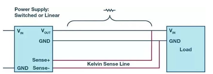
Figure 1 shows that there is resistance between the power supply and the load. The voltage loss on this resistor can be compensated by slightly increasing the voltage generated by the power supply. Unfortunately, the voltage drop generated on the line resistance depends on the load current, that is, the current flowing through the line. A high current results in a higher voltage drop than a low current. Thus, the load is powered by a regulating voltage with fairly low precision, which depends on the line resistance and the corresponding current.

Figure 1. Physical distance between the regulator and the associated load.
There has long been a solution to this problem, which can be connected in parallel with the actual connection, adding an extra pair of connections, and using Kelvin detection lines to measure the voltage on the electronic load side. In Figure 1, these extra lines are shown in red. These measurements are then integrated into the power supply voltage control on the power supply side. This method is effective, but the disadvantage is that additional detection leads are required. Since there is no need to carry a high current, the diameter of such leads is usually very small. However, setting up the measuring line in the connection cable to get higher currents brings additional work and higher costs.
The voltage drop on the connection line between the power supply and the load can also be compensated without an additional pair of detection leads. This is particularly relevant for applications where cabling is complex, expensive, and the resulting EMC interference is easily coupled to voltage test leads. The second option is to use a dedicated line voltage drop compensation IC such as the LT6110. Plug this IC into the voltage generation side and measure the current before it enters the connection line. The output voltage of the power supply is then adjusted according to the measured current, so that the load side voltage can be adjusted very precisely, without considering the load current.

Figure 2. The LT6110 is used to adjust the power output voltage to compensate for the voltage drop on the connection line.
With components such as LT6110, the power supply voltage can be adjusted according to the corresponding load current; However, this adjustment requires information about line resistance. Most apps provide this information. If the cable is replaced with a longer or shorter cable during the lifetime of the device, the voltage compensation achieved with the LT6110 must also be adjusted accordingly.
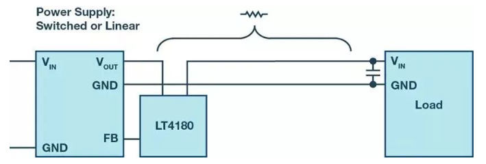
If the line resistance is likely to change during device operation, components such as the LT4180 can be used to virtually predict the connection line resistance with an input capacitance on the load side, providing a high-precision voltage to the load side.

Figure 3 shows an application using the LT4180 where the resistance of the transmission line is unknown. The line input voltage is adjusted according to the corresponding line resistance. With the LT4180, there is no need for Kelvin detection of the line, and voltage regulation can be achieved by gradually changing the line current and measuring the corresponding voltage change. The measurement results are used to determine the voltage loss in the unknown line. The output voltage of DC/DC converter can be optimized according to the voltage loss information.
The required DC accuracy can be improved with additional Kelvin detection lines. In addition, integrated circuits can also be used to compensate for voltage drops on the line without the need for Kelvin detection lines. This solution can be useful if the cost of Kelvin inspection lines is too high, or if existing lines must be used and no additional inspection lines are available. With these design tips, higher voltage accuracy can be easily achieved.
Previous: Automotive PCB circuit board
Next: Flexible Printed Circuit
Hot Products
Navigation
+86 134 0021 8776
Floor 9, Aupu building, No. 395 XinShi North Road, Shijiazhuang Hebei, China
Request a Quote
